


|
Introduction
Summary of LASCO/EIT What is LASCO? What is EIT? (external link) FAQ Realtime Images RealTime Movies (SOHO Movie Theater) Download LASCO Data Data Products Image Gallery Movie Gallery Processing Levels FITS Header Keywords Data Policy Wavelet images/movies Coronal Mass Ejections Eclipse Observations LASCO Calibration LASCO C3 Planet transits (via Sungrazer) Team and Operations Resources LASCO/C1 at MPAe (Germany) LASCO at LAS (France) LASCO Handbook Technical Notes Detailed Documentation Acronyms Solwind Images and CMEs SOHO Home page SOHO and SOHO Instruments Other Solar Satellites and Observatories |
Chapter 5. C2 TelescopeThe C2 optical design is adapted from earlier, well developed coronagraph designs, ultimately deriving from the fundamental work of B. Lyot and J.W. Evans. A particular source was a miniaturized coronagraph concept, designed and tested but ultimately not flown, for the ISPM (Solar Polar, now Ulysses) imaging experiment. The C2, like C3, is externally occulted. This approach, in which an external occulting disk assembly completely shadows the objective lens from photospheric light, has the advantage of dramatically lowering levels of stray scattered light. This is necessary for observations at elongations from the Sun greater than those viewed by C1, because the intrinsic brightness of the corona decreases very rapidly (about rE-3.5). The main disadvantage of external occultation is that the imaging properties of the objective lens are degraded by vignetting (partial obscuration of the aperture by the external occulter) for object points not far away from the occulter shadow. In other words, the instrument achieves full resolution at the outer part of its field, but relatively poor resolution nearer the inner edge. It is considerations such as this that drive the requirement for extensive overlap of all three of the LASCO telescopes. Where one is weak, another excels, and all are mutually dependent on cross calibration in the overlap regions.
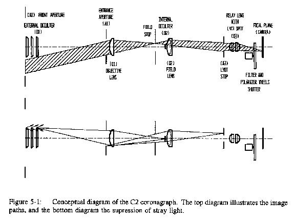
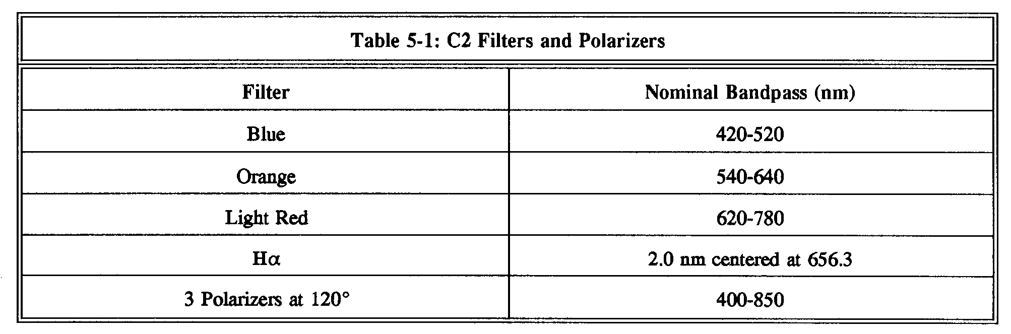
5.1 C2 opticsA conceptual diagram for C2 is illustrated in Figure 5-1 (low resolution) or Figure 5-1 (high resolution). The top diagram traces a selected ray bundle for the coronal image, while the lower diagram illustrates the optical elements and ray paths involved in the suppression of stray light. Beginning at the left of each diagram, the external occulter D1 completely shadows the entrance aperture A1 from direct sunlight. The D1 occulter is a threaded conical cylinder, which acts similarly to a stack of closely spaced disks. The objective lens O1 is an achromatic doublet whose elements have been joined in optical contact to avoid possible scattered light from optical cement. The objective lens images the corona in its rear focal plane. A field stop here defines the 6.0 Rsun outer field limit. The O1 objective lens also images D1 onto a stop D2 at a distance behind the coronal image. This D2 internal occulter intercepts residual diffracted light originating at the tapered multiple edges of D1. A short distance behind D2 is a field lens O2, which collimates the primary coronal image, and also images A1 onto the Lyot stop A3. The Lyot stop intercepts diffracted light originating at the entrance aperture A1. Finally, a relay lens O3 behind A3 re-images the primary coronal image onto the 1024x1024 pixel CCD camera at the image plane. The front surface of the O3 relay lens also carries the Lyot spot. This is a small, opaque spot on the optical axis which intercepts a small ghost image of D1 produced by interreflections in the O1 objective lens, a non- negligible source of stray light. The 0.021 mm square pixel size of the CCD subtends an angle of 11.4 arc seconds in the coronal image. The 6.0 Rsun outer field approximately circumscribes the CCD square imaging surface. The total length of the C2 optical path requires the use of folding mirrors to fit it into two adjacents quarters of the Coronagraph Optics Box (see further in Chapter 7, and Figure 7-1). Two flat mirrors, M1 and M2, are used to fold the optical beam. They are coated with a low-polarizing film to avoid introducing significant instrumental polarization. Filter and polarizer wheels, and the shutter, are located in the space between the relay lens and CCD camera. C2 does not have a narrowband, spectroscopic quality filter. As an aid to separation of F from K coronal light, however, it has broadband color filters and polarizers for polarization analysis, as does C3. A moderately narrow (2 nm) H-alpha filter is included. The filter wheel contains the blue, orange, light red, and H-alpha filters, and a lens in the last position which is used to image the external occulter for certain calibration measurements. The polarizer wheel contains three polarizers at 120 degrees, a clear glass position, and a neutral density filter used in conjunction with the filter wheel lens. The four filters are used with the clear glass polarizer wheel position or one of the three polarizers. Table 5-1 lists the bandpasses (FWHM) of these filters. Internal calibration lamps (redundant) are located behind the shutter. When powered, light from the lamps will be reflected diffusely from the rear of the shutter blade, pass through a filter and a polarizer, and then illuminate the CCD. The signal level of the CCD detector can be monitored when the front door is closed. In this case, the coronagraph will see the rear of a small, Sun- illuminated diffuser set in the door. This patch will be out of focus at the CCD, but provides a known level of solar disk illumination. A critical consideration for C2 is precise alignment of the optical axis to the center of the Sun. The axis is taken as a line drawn through the centers of the external occulting assembly D1 and the entrance aperture A1. Thus, when the axis is pointed directly at Sun center, the external occulter shadow falls precisely centered on A1. This condition will be taken as the criterion for proper alignment of LASCO. A further description of the alignment process for LASCO is given in Chapter 7. |
